
electronics-journal.com
19
'25
Written on Modified on
Daisy Chaining for parallel connection of DIN Rail power supplies- considerations and limitations
.
www.delta-emea.com
Daisy Chaining is a commonly used term which defines a connection method of multiple devices, such as power supplies, in a sequential fashion. In the following article we will explain how to connect power supplies (PSUs) in a daisy chain format for industrial applications and the limitations to be considered.
PRINCIPLE
Daisy chaining for power supplies is defined as a wiring connection scheme in which several PSUs are directly connected in parallel fashion in order to provide sufficient current for the load. In this wiring principle, the outputs of each power supply are “looped through” (chained together) to deliver the total current to the load.
SETTING UP
To ensure a reasonable level of current sharing between power supplies in a direct parallel connection system it is important to accurately set the output voltage of each power supply to match each other as closely as possible.
Each power supply should be set up independently when connected to a load equivalent to 100/n % where n is the total number of power supplies. E.g.for 2 power supplies it would be 50%.
Ideally each output should be set to within 25mV of each other. With accurate set up a sharing ratio of 60%/40% can be achieved.
Bear in mind that, over time, the settings can drift due to various ageing tolerances, which can cause system instability – therefore periodic recalibration is recommended whenever practical.
LIMITATIONS
i.) Some Din Rail power supplies cannot be connected directly in parallel. Hence, it is necessary to check the datasheet / instruction manual before implementing a power supply system according to the daisy chain method. If this checkpoint is ignored, there could be a serious safety risk which can lead to a fire hazard due to overloading. If in any doubt, check with the manufacturer.
ii.) If direct parallel connection is possible then special attention should be paid to the rating of the output connection terminals of the power supplies. A key factor here is that the total load current of the system will be carried by the output terminals of last power supply in the daisy chain. For example, connecting 3 x 10A power supplies in parallel will result in 30A at the last power supply (at maximum load). Therefore, the maximum current specified for the output terminals must not be exceeded.
A second crucial factor is to ensure that the gauge of the wire (current carrying capacity) from last power supply to the system load is sufficiently rated and can be accepted by the output terminals.
EXAMPLE
Many Delta DIN rail power supplies come with 2 positive and 2 negative DC output terminals, which are ideally suited for daisy chain connection by eliminating the need to double up wires into one terminal. (Refer to Fig-1)
For example, the Force-GT (DRF) is a new series of Delta DIN rail power supply. On the DRF-24V240W datasheet (rated at 24VDC 10A), the maximum current rating of the output terminal is specified as 30A but the maximum wire gauge accepted is 12 AWG which has a current rating of 22.5A,which becomes the limit that DRF-24V240W connected in daisy chain mode can safely provide.
3 power supplies connected together could nominally deliver up to 7.5A each, subject to the sharing tolerances of the system.
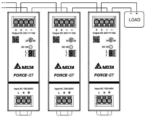
Fig-1: DRF-24V240W with Daisy Chain
If more than 2 x DRF are to be connected in parallel then it is recommended that circuit breakers, fuses, diodes or a redundancy module should be fitted to each output as a precautionary safety measure.
ALTERNATIVE METHOD
Another method is to use an appropriately rated load distribution terminal block. In this way, all outputs of the power supplies are connected in a star wiring fashion to the distribution terminals separately. Therefore, the wire gauge limitation of maximum current for the power supply output terminals is no longer a consideration. (Refer to Fig-2)
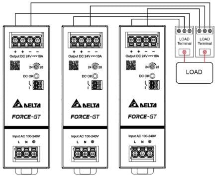
Fig-2: DRF with star wired Distribution Terminals
For local purchase and service of industrial and medical power supplies, please contact our authorized distributors at https://deltapsu.com/en/contact/find-a-distributor.
